Showing posts with label custom OBD2. Show all posts

Wednesday, April 16, 2014

Subaru ECU Placement - Rear Passenger Tail Light Compartment

I've decided to re-position my Subaru ECU in the passenger tail light compartment that is opened up when the VW engine, relay and air snorkel are pulled out.  Here's a basic photo of the protective ECU box I'm installing and its location in the engine bay.

ECU box placement in rear passenger tail light compartment

Many people do not want to put their Subaru ECU in the engine bay, citing things like "the elements will ruin your ECU" or "VW engineers did not put ECUs in the engine bay and they know best".  Well, that was the 1980s and things change as technology and innovation advances.  Besides, if VW engineers know "best", why am I replacing their engine with a Subaru?  :)

Subaru/Vanagon conversion experts likeVanaru (Vanaru.com), Ben @ (benplace.com) and Paul Guzyk (BoulderHC.com), do every conversion this way and are quite successful at it.  I personally chose this location for many reasons:
  1. The wiring harness ends up clean and straight forward - essentially, the wiring harness becomes a true plug-and-play, turn-key installation.  Initially, I went with a RMW harness (their default location for the ECU is in the rear bench seat), but this solution ends up being two harnesses, one for the main engine and another separate sub-harness for the ALT, voltage sensor, AC compressor, starter, fuel pump, and coolant level sensor.  After seeing the slick turn-key solution provided by Vanaru that easily combined all these into a single harness, I just had to redo it that way!
  2. This single, wiring harness is visible 100% from the engine bay rather than having some portion of it tucked away behind the firewall.  I like being able to easily inspect my harness without getting under my van.
  3. The wiring harness wraps around the back and top of the engine bay, staying out of the way of road hazards.  In contrast, when locating the ECU in the rear bench seat, the wiring harness is exposed to these hazards between the firewall and bench seat opening.
  4. It utilizes the newly opened space in the engine bay that would be wasted otherwise.
  5. It opens up room for storage in the rear bench seat or closet, which are two other common locations for Subaru ECUs.  That said, I'm a storage Nazi.  For instance, I'm also removing my rear heater to open up even more space under the rear bench seat. You may not care about storage like I do.
  6. Diagnostic ports (OBD2 and the proprietary Subaru ones) are more easily reached right in the engine bay compared to the rear bench seat area.  So, a mechanic can more easily scan & reset codes from this location.
The photo here shows how I plan to layout the harness.  It is based on the Vanaru design.  It will be basically the same except where noted in RED.  I'll be tying in my ALT harness into the main harness a little differently.

Example Vanaru conversion that I'll be using as a prototype for my wire harness layout and ECU box placement

If you put your ECU in the engine bay, you need to protect it from the elements!  I describe how I am doing this with full step-by-step DIY "how to" here:  http://westycamper.blogspot.com/p/ecu-box.html


Friday, March 21, 2014

Wiring Up VSS and OBD2

Here are my plans to wire up VSS and OBD2 connector from the rear of the van to the front.  It is important to have a good signal for the VSS, so shielded 18 AWG copper wire protected by OEM level sheathing was chosen.  The cable has 6 wires, so the other 3 will serve to send OBD2 power, ground, and codes signal from the rear to the front.  There are only 3 wires required for Subaru codes, so I am going to cut a regular OBD2 cable, splice the three wires I need to send, and only route those to the front female connector.  Also, I have a Subaru diagnostic port (includes an female OBD2 connector, of course) that I found at a UPull & Pay for $2.  I'm going to split the signal to that port as well so mechanics working in the back of the van will also have a signal.

A., B, and C. are all housed in a water-proof poly-carbonate case along with the Subaru ECU.
Depending on whether the 3 PIN connectors are put into the VW black box or kept exposed in the engine bay will determine the quality of connector I use.  At the front of the van, all the wires are protected under the dash, so they will be standard connectors.

Last, I will actually be running 2 cables (e.g., 12 wires total) under that van.  The spare wires will come in handy when hooking up Subaru Cruise Control and aftermarket gauges when the time comes.


Wednesday, February 26, 2014

Small Car Interface Board


EDIT July 7, 2014: The SC interface board does not eliminate the common P0461 - Fuel Level Sensor code.  The ECU requires variable voltage (e.g., low vs. high) and the SC interface board only sends constant volts.  This is a shame.  It will not eliminate all codes related to the conversion!

After several calls to Small Car, I have my interface board setup.  The legend they ship with the product has much to be desired, but Mao at SC was super helpful over the phone. So kudos to SC customer support.  ** My car is a 2001 Subaru Legacy and these mappings may not work for other models.

RMW Wiring Harness Wires Mapped to SC Code Eliminator Board


Subaru Wiring Harness wires set into the SC code eliminator board

Alternator Wiring Harness

Here's my Subaru/Vanagon alternator harness design.  The main RMW wiring harness does not include the ALT, starter, fuel pump, A/C compressor, voltage sensor or coolant level sensor!  So, I had to create my own sub-harness for these and figure out how to integrate them into the VW and main wiring harness.  This took a lot of brain cycles, hence my posting here to help others in the same predicament.

I am looking for a better way to do my wiring harness, in general, to make it a more turn-key install rather than two separate harnesses like this.  I'll keep you posted!

EDIT April 16, 2014: 
With the new decision to place my Subaru ECU in the rear passenger tail light, I can combine this sub-harness described here directly into the main Subaru harness.  What does this mean to my original design here?  For one, the fuel pump wire is shorter and directly connected to the ECU and their is no need to have the extra "pluggable" connectors since the wiring will be one main harness rather than the two.   Since it is now one, single harness, it all goes into the black box in a single location, so no need to mess with the extra black box grommet.

For more info, see my new solution here:  
subaru-ecu-placement-rear-passenger


A sub-harness is required when integrating a RMW wiring harness because it does not include these components

Tuesday, February 25, 2014

Need to wire this up... What pins are really required!?


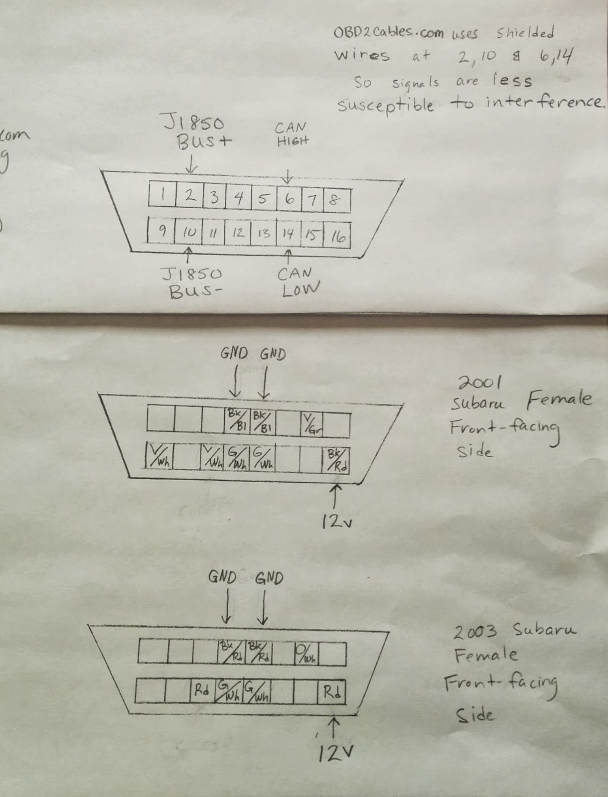
Currently, I'm struggling with how to connect the least # of OBD2 wires from the engine bay of my van to the front, where I will have a diagnostics port available near the dash.  Paul Guzyk mentioned that a mechanic is going to want to plug in their favorite scan tool up front and drive around to diagnose a problem and that made perfect sense.  However, I don't want to run 7-8 OBD2 wires all the way up front, so I need to get only the ones I really care about out of these connectors!

Subaru pin-outs vs. OBD2Cables.com pin-outs

These are all 'front-facing' on the female connector.  Neither of the Subaru OBD2 connectors have pins in then 2,10, 6, or 14 positions.  These are the positions OBD2Cables.com uses for their shielded 'signal' wires.  They are shielded to prevent interference when transferring the codes, etc. to and from the ECU.

Also, curious as to why my 2001 Subaru has an extra pin (Violet/White wire in pin #9) that the 2003 Subaru connector does not.  I have no idea why.

OBD2Cables.com vs. 2001 Subaru vs. 2003 Subaru


When comparing an online guide to Subaru pin-outs to my Subaru connectors, I see a big difference.  For instance, neither of my connectors have pin 6 or pin 15.  My Subaru connectors do have pin 7 (K-LINE) in common with the table, which might imply signals are sent over pin 7; however, this is not how OBD2Cables.com builds their cables (see above).  If it were so, OBD2Cables.com would have shielded wire for pin 7 as well.

UPDATE: April 16, 2014 - I chose 5, 7, and 16 based on this chart.  
Note:  Hans at Vanaru recomended also wiring up 4, which is a GND as well.